
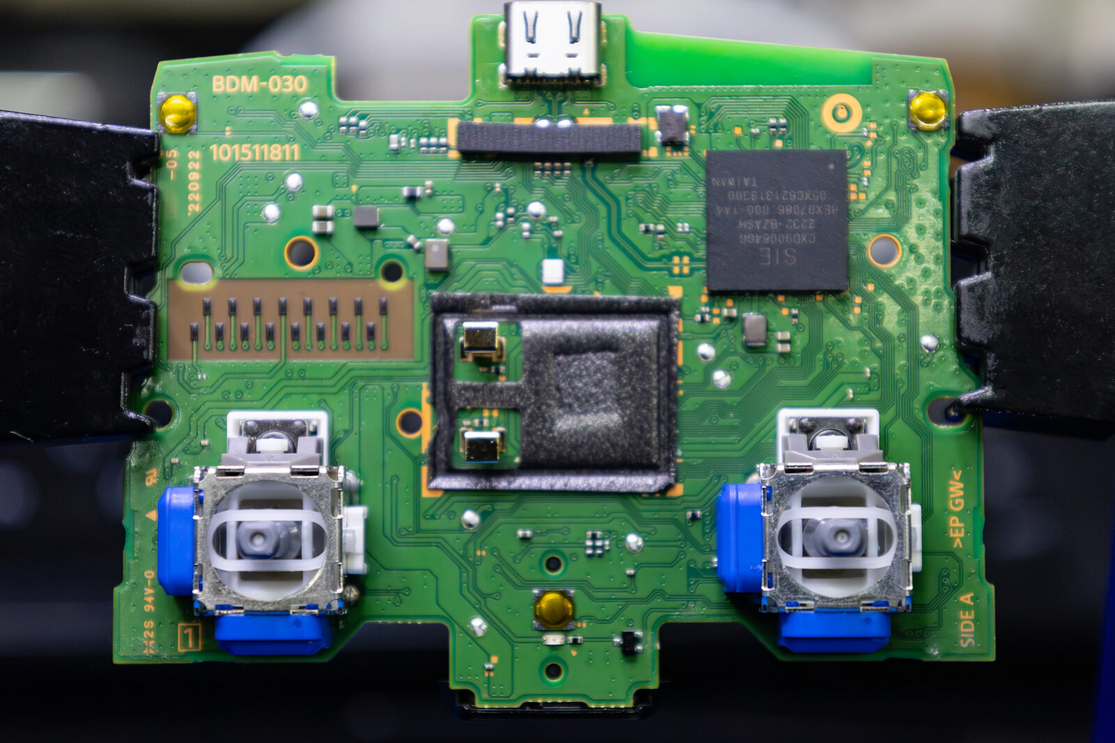
Replacing a PS5 DualSense joystick module is the only permanent fix for stick drift. Whether you’re fitting a like-for-like OEM ALPS potentiometer or upgrading to a contactless TMR (Tunnel Magnetoresistance) module from suppliers like GuliKit or Ginfull, the desoldering and soldering process is identical - the module footprint hasn’t changed across any DualSense revision.
If you haven’t decided which replacement module to use, our stick drift repair guide covers the differences between ALPS, TMR, and Hall Effect modules in detail - including a full comparison table, supplier recommendations, and why TMR is the preferred upgrade for a permanent, drift-free fix.
This guide focuses purely on the hands-on work: how to get the old module off the board and the new one on. It covers three desoldering methods, and we are not going to pretend they’re equals.
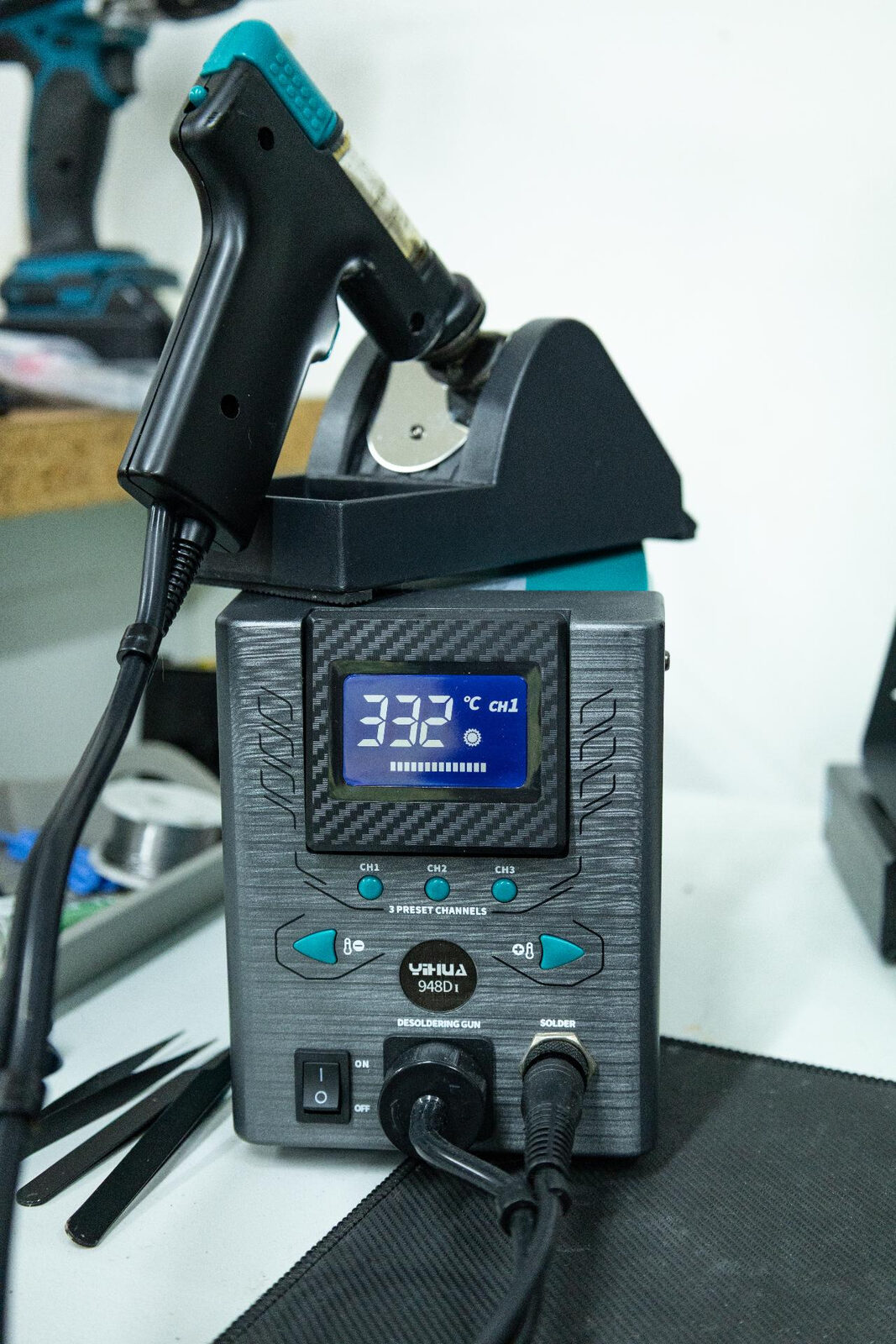
Use a desoldering gun. Something like the Yihua 948 heats one pin at a time and vacuums the factory solder straight out of the hole. It is precise, it is quick once you’ve got a rhythm, and it leaves you with clean, empty through-holes and no drama. If you only buy one tool for this job, buy that one.
The iron and wick method is the fallback when the gun isn’t an option. It works, but it is slow and it is where most first-timers come unstuck.
Hot air we would actively steer you away from for this particular repair, and we’ll explain why below. The short version: the joystick module body is plastic, and hot air melts it.
Before You Start: Understanding the Challenge
The DualSense joystick module is a 14-pin through-hole component with additional grounding tabs. It sounds straightforward to desolder, but there are two factors that make it harder than most through-hole work.
First, Sony uses lead-free solder on the DualSense motherboard. This is required by the EU’s RoHS directive (Restriction of Hazardous Substances), which banned lead-based solder in consumer electronics from 2006 onwards. Lead-free solder - typically Sn96.5/Ag3/Cu0.5 - has a melting point of around 217°C, compared to 183°C for traditional 63/37 leaded solder. That higher melting point means more heat, longer dwell times, and a greater risk of damaging the board.
Second, several of the joystick module pins connect directly to the ground plane - a large continuous copper layer inside the PCB. The ground plane acts as a massive heat sink, absorbing thermal energy faster than your iron or hot air can deliver it. This is why beginners often find that some pins reflow easily while others stubbornly refuse to release, even at high temperatures. The temptation is to crank the heat up. Don’t. That’s how boards get cooked.
The solution to both problems is the same: low-melt bismuth solder paste.
The Low-Melt Bismuth Paste Technique
Low-melt solder paste - typically Sn42/Bi58 with a melting point of 138°C - is the single most important consumable in your desoldering toolkit. Understanding how it works will save you from destroyed boards and hours of frustration.
When you apply bismuth paste to the existing lead-free joints and heat the area, the paste melts first at 138°C and becomes liquid. That liquid bismuth-tin alloy then begins to dissolve the solid lead-free solder through a metallurgical process called dissolution. The liquid phase gradually absorbs tin and silver atoms from the solid solder at the interface - the same way water dissolves salt without needing to reach the melting point of salt.
As more of the factory solder dissolves into the liquid, the joint transitions from solid to liquid without ever needing to reach the original 217°C melting point. In practice, you’re working at around 160-180°C. This is transformative for the ground plane pins that would otherwise act as impossible heat sinks - sustaining 170°C through the ground plane is far easier than trying to push 220°C+ through it.
Apply the bismuth paste generously. More liquid phase means faster dissolution of the solid solder. Don’t be stingy with it.
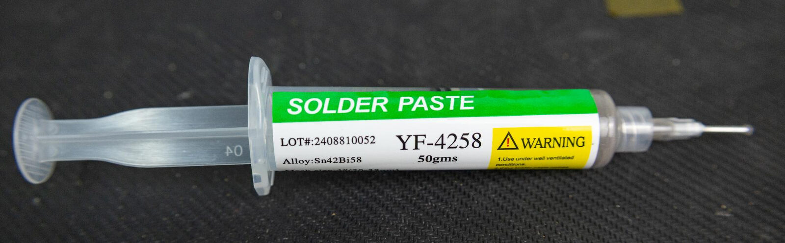
One thing worth clearing up early, because plenty of guides get this wrong: bismuth paste is already fluxed. You do not need to layer tacky flux on top of it to make it work. It doesn’t ball up, it doesn’t sit there sulking, it just wets into the joint and gets on with dissolving the factory solder. Flux earns its place later in the job, when you’re putting the new module in. On the desolder side, the paste is doing the work.
Consumables You’ll Need
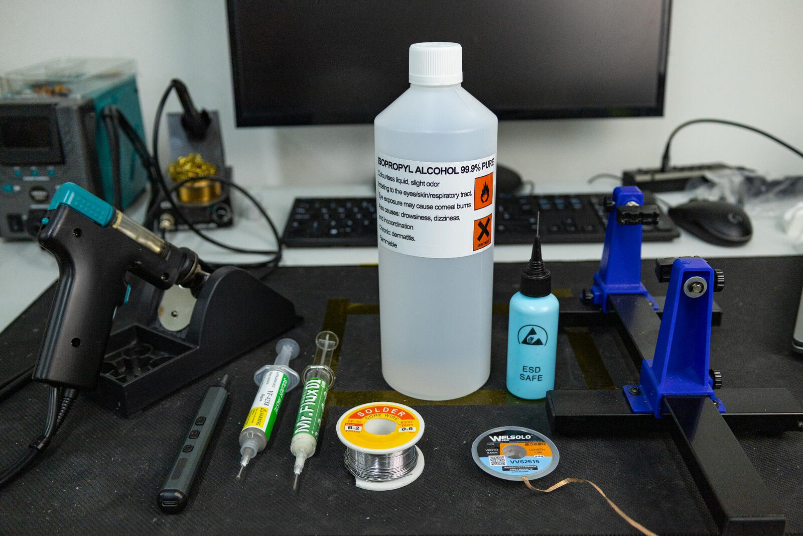
Before starting any of the methods below, make sure you have the following on your workbench:
| Item | Purpose | Notes |
|---|---|---|
| Low-melt bismuth paste (138°C) | Applied to pins before desoldering to lower the melting point of factory solder | Sn42/Bi58 composition. The one thing you cannot do this job without. Already fluxed, so it needs no help |
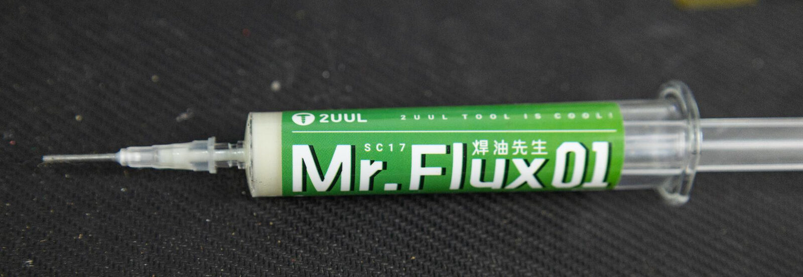
| Tacky flux paste (syringe) | For the install side, and for making solder wick actually absorb | No-clean type recommended. 2UUL Mr.Flux 01 or similar. Not needed on top of bismuth paste when desoldering |
| Leaded solder wire (63/37, 0.6mm) | For resoldering the new module | 63/37 eutectic gives the cleanest joints. 0.6mm diameter for precision on fine-pitch pins |
| Solder wick / braid | Cleaning residual solder from through-holes, if your method leaves any behind | Store in a sealed bag to prevent oxidation |
| Kapton tape or aluminium foil | Shielding nearby plastic connectors and sensitive components from heat | Particularly important for the battery connector and ribbon cable sockets near the joystick |
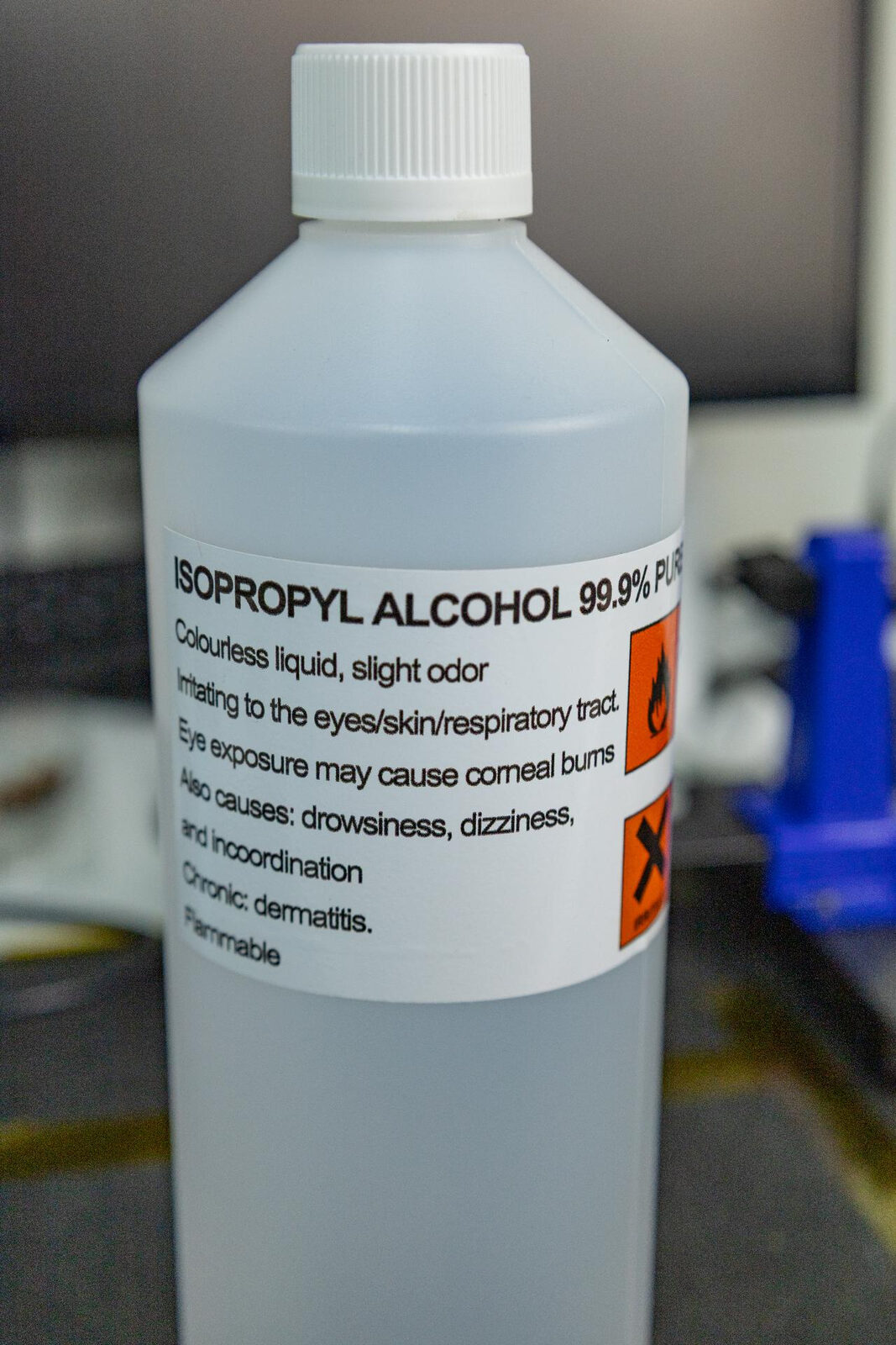
| Isopropyl alcohol (99%+) | Cleaning flux residue after soldering | Optional with no-clean flux but makes visual inspection easier |
You Are Going to Need a Real Soldering Iron
Whatever you use to get the old module off, you need a soldering iron to put the new one on. This is the part people skip past, and it’s the part that decides whether the finished board looks like a repair or looks like an accident.
Those 14 through-holes are big, and several of them are tied straight into the ground plane. When you feed solder into one of those holes, the copper underneath is trying to pull the heat away from your tip faster than you can put it in. A cheap 30W pencil iron from a hardware shop cannot win that fight. It’ll idle at a nice number on the dial, then collapse to nothing the moment it touches the pad, and you’ll be left prodding a dull grey blob wondering why it won’t flow.
What you actually want is a cartridge iron - one where the heating element and the tip are the same part, sitting right at the business end. That’s what gives you thermal recovery: the ability to dump heat into a joint and immediately get the tip temperature back.
As a minimum, a T12 station that holds 350°C under load. T12 cartridges are cheap, widely available, and there are plenty of decent stations built around them. At 350°C with a chisel tip, a T12 will flow solder into the ground pins without you having to lean on it.
If you can stretch to it, go C245. The JBC-style C245 cartridge is the step up: faster recovery, better tip selection, and it simply does not sag when it hits a ground plane. Genuine JBC gear is expensive, but the C245 cartridge format is used by a lot of far cheaper stations and handles, and the cartridges themselves are inexpensive. For anyone doing more than one or two controllers, it’s the tool that stops the install side being the hard part.
Stations in this class often ship with two handles, a C245 and a smaller C210. Use the C245 for this job. The C210 is a fine-work handle meant for tiny SMD components, and it has nowhere near the thermal mass to win an argument with the ground plane on a joystick pin. It will earn its keep elsewhere on a controller board, just not here.
Either way, fit a chisel or bevel tip rather than a fine conical point. Surface contact area is what moves heat. A needle-sharp tip looks precise and transfers almost nothing.
Preparation (All Methods)
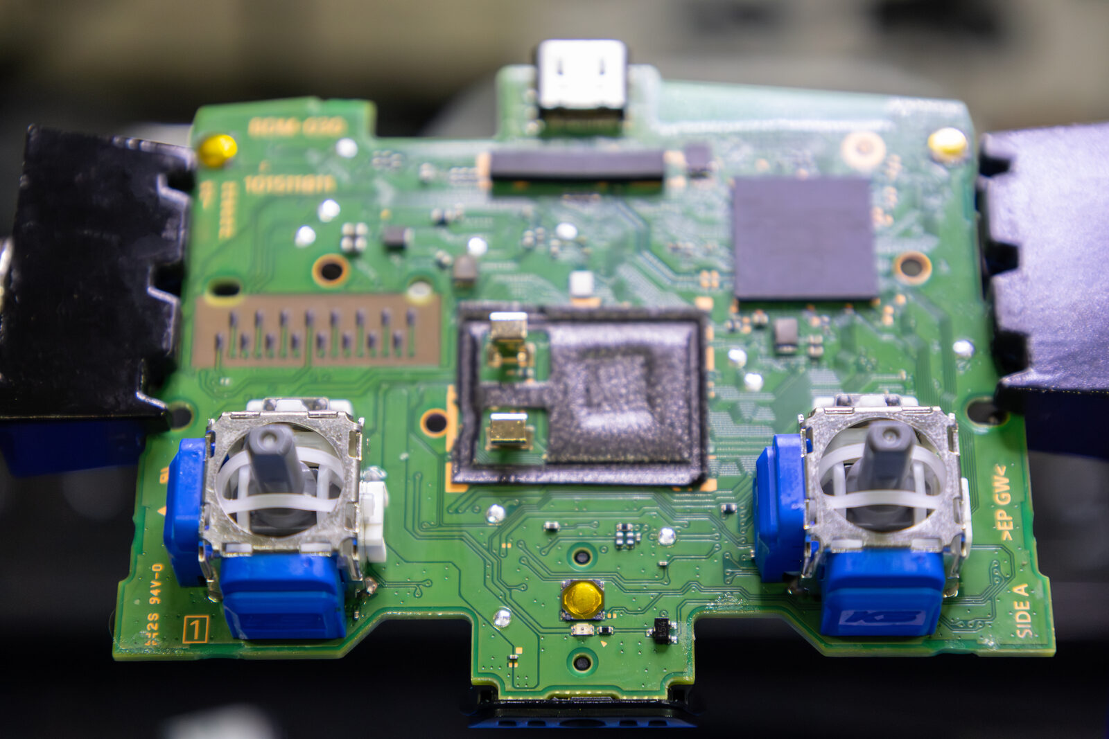
These steps apply regardless of which desoldering method you use.
Remove the DualSense motherboard from the shell completely. Don’t attempt to desolder with the board still in the housing - you’ll melt plastic, block access to pins, and make the job far harder than it needs to be.
Identify the joystick module pins on the underside of the board. There are 14 through-hole pins plus grounding tabs.
Shield nearby components. Use kapton tape or a small piece of aluminium foil to protect any plastic connectors, ribbon cable sockets, or sensitive components adjacent to the joystick module. The battery connector and flex cable sockets near the joystick are the main ones to watch.
Secure the board in a PCB holder or helping hands. You need both hands free throughout this process.
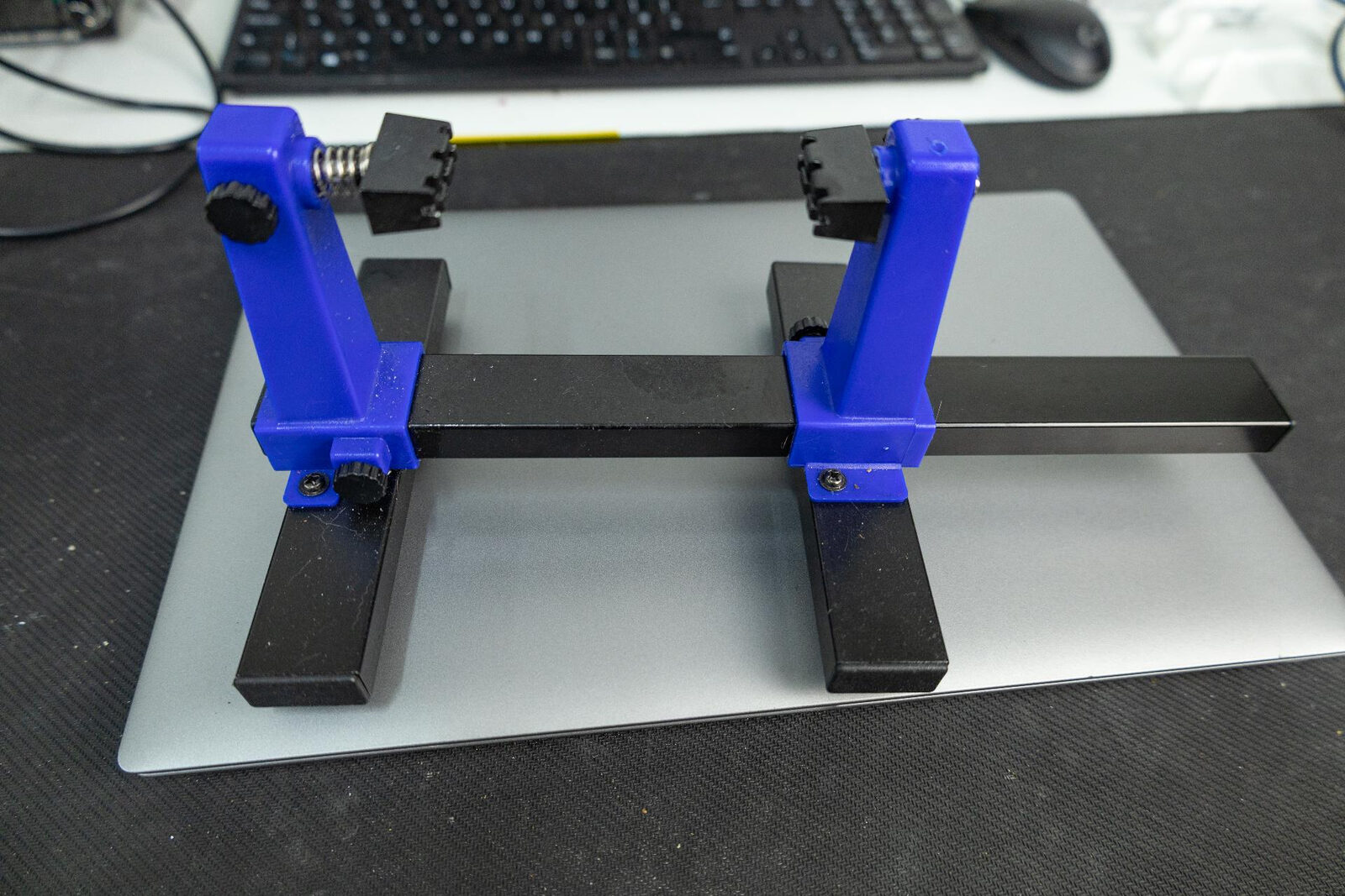
Make sure you can actually see the work. The joystick pins sit close enough together that a solder bridge between two of them is essentially invisible at arm’s length, and you cannot fix a cold joint you were never able to spot. This is not a place to squint and hope.
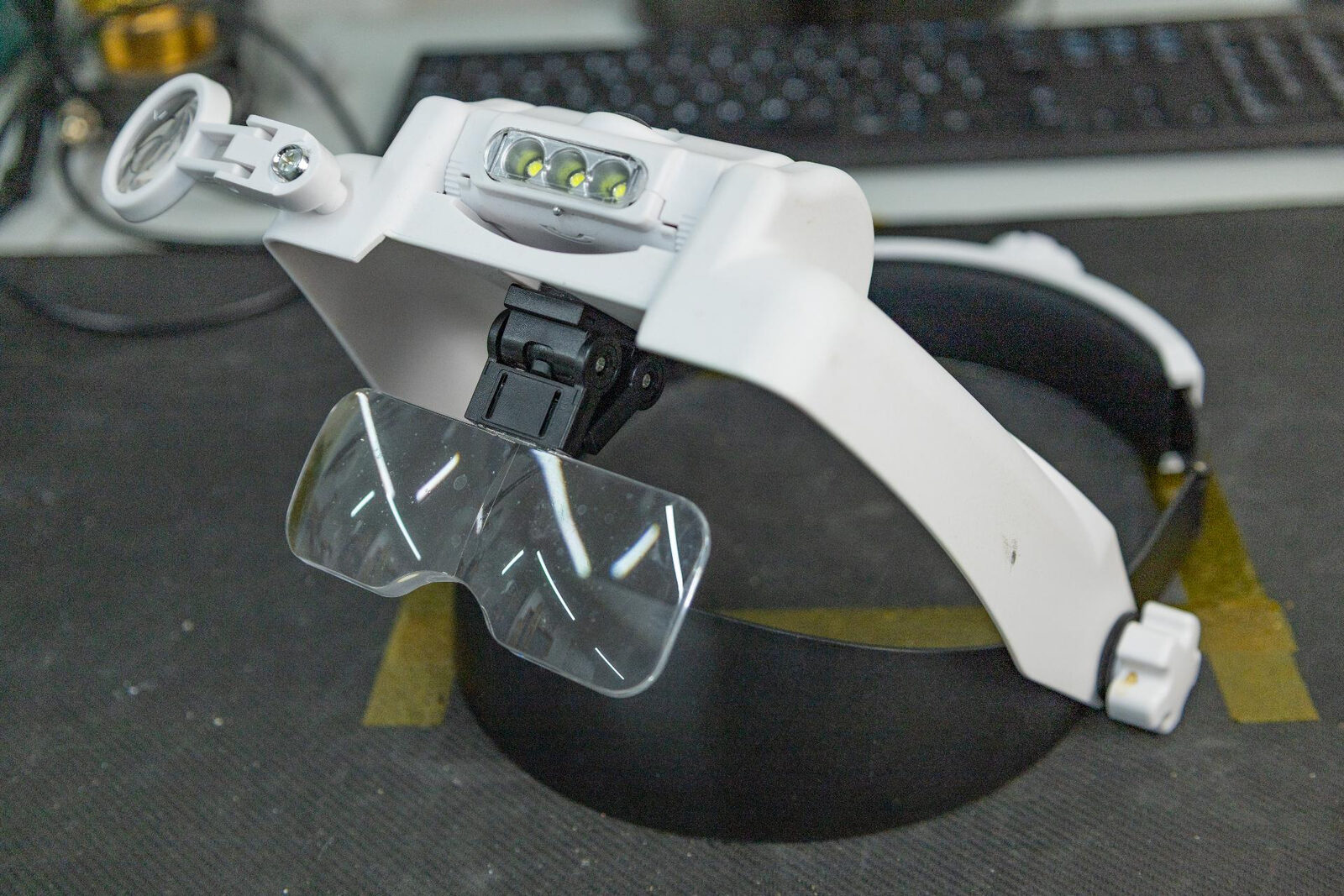
A LED head magnifier like this costs about as much as a takeaway and is the cheapest upgrade to your work you can buy. The next step up is a stereo microscope, which is what you will end up wanting if you do this regularly, and which costs rather more than a takeaway. Start with the visor and see how far it gets you.
Have your replacement module, solder, and wick all within reach before you start heating anything.
Method 1: Desoldering Gun (Recommended)
The desoldering gun is our recommended approach for joystick module removal, and it isn’t close. A dedicated desoldering station like the Yihua 948 heats each pin individually and vacuums the molten solder out of the through-hole.
The thing nobody tells you about this method is how little heat actually goes into the board. You’re not warming up a whole area and hoping for the best - the heat goes exactly where it’s needed and nowhere else. Each pin takes a few seconds of contact to reflow and vacuum out the factory solder, and then you move on. Overheating the board barely enters into it. What you’re left with, pin by pin, is a clean, empty, shiny hole.
For anyone building a controller repair workflow, the investment pays for itself quickly in time saved and boards not destroyed.
Stage 1 - Apply Low-Melt Bismuth Paste
Apply bismuth paste to all 14 pins on the underside, plus the grounding tabs. Strictly speaking you can do this job without it, since you’re attacking one pin at a time and direct contact will overpower even a ground pin eventually. But “eventually” is doing a lot of work in that sentence. With the paste on, every pin releases faster and at a lower temperature. Use it.
No flux on top. The paste is fluxed already.
Stage 2 - Set Temperature
Set the desoldering gun to roughly 280-320°C with bismuth paste applied, or 350-380°C without it. Let the gun come fully up to temperature before you start - a gun that’s still climbing will waste your first two or three pins.
Stage 3 - Desolder Each Pin
Place the desoldering gun tip directly over one pin, making sure you’ve got a good seal between the tip opening and the board surface. Wait two or three seconds for the solder to go liquid - you can see it happen - then trigger the vacuum. The molten solder gets sucked up into the gun’s collection chamber.
Move to the next pin and repeat. Work your way around all 14 pins systematically so you don’t lose track of which ones you’ve done.
For ground plane pins that feel stubborn, hold the tip in contact for a couple of seconds longer before triggering. Direct contact transfers heat far more efficiently than hot air, so the pin will give in - the heat is going straight into the joint rather than being sprayed across the board.
Stage 4 - Check and Clear
After doing all pins, gently test whether the module is free. If it’s still held, one or more pins still have solder in them.
Give the stubborn ones more bismuth paste and hit them again. That’s the fix nine times out of ten - fresh paste, another few seconds of contact, another pull on the vacuum. Adding a touch of fresh leaded solder to the pin before you go again also works, because it increases the volume of liquid and gives the vacuum something to grab.
Once all pins are clear, the module lifts straight out.
Common Desoldering Gun Mistakes
Bad seal between tip and board. If the tip doesn’t sit flush around the pad, the vacuum won’t pull solder effectively. Use a tip size that matches or is slightly larger than the pad diameter.
Triggering the vacuum too early. If the solder hasn’t fully melted, the vacuum pulls air and achieves nothing. Wait until you see the solder go liquid.
Not cleaning the gun. Empty the solder collection chamber regularly. A clogged chamber reduces vacuum power. Clean the inside of the tip frequently too - solder builds up and restricts the opening.
Being stingy with the bismuth paste. If a pin is fighting you, the answer is more paste, not more temperature. Paste costs pence. Pads do not grow back.
Bonus: Using the Desolder Gun to Reflow Joints
The desoldering gun isn’t just for removing solder - it’s also excellent for correcting bad solder joints after you’ve installed the new module. If you’ve got a joint that looks dull, blobby, or poorly formed, place the desolder gun tip over it briefly to reflow the solder. The heat from the tip melts the existing solder and the vacuum action draws it into a clean, well-formed joint around the pin. It’s a quick way to tidy up your work without needing to add or remove any solder, and it produces consistently neat results.
Method 2: Soldering Iron and Solder Wick
Search around online and you’ll find no shortage of people telling you this method is easy. It is easy, in exactly the way that parallel parking is easy: when you’ve done it a hundred times, with the right kit, on someone else’s car.
Here’s what every one of those videos leaves out.
The ground plane will pull heat out of the joint faster than a budget iron can put it in.
That is the whole problem, in one sentence. Read it twice. Every single way this method goes wrong is downstream of that one fact.
It is not a matter of technique, or patience, or watching the video again more carefully. It is a race between the copper and your iron, and with the wrong iron you lose it before you start. The pad never gets hot enough to release, no matter how long you sit there.
And sitting there is exactly what you’ll do. You’ll have the tip pressed against the wick, watching nothing happen, and the natural response is to press harder and stay longer. That is the worst thing you can do. Sustained heat plus mechanical pressure on a pad is the recipe for lifting it clean off the board, taking the trace with it. A lifted pad turns a forty-minute stick swap into a jumper-wire repair that needs a microscope and a steady hand.
So this is the honest position: this method is fine if you have a proper cartridge iron, a chisel tip, and some experience reading how a joint is behaving. It is not the method to learn on. If your plan is to fix your one beloved controller using the iron that’s been in the shed since your dad bought it, the odds are not with you. Buy the desoldering gun, or find someone who has one.
If you’re going ahead anyway, do it like this.
Stage 1 - Apply Low-Melt Bismuth Paste
This is not optional here. Without bismuth paste, trying to pull lead-free solder off ground plane pins with an iron is an exercise in slowly cooking a board. Apply it to all 14 pins.
Stage 2 - Add Fresh Leaded Solder
Using 63/37 leaded solder at 0.6mm, add a small amount of fresh solder to each pin on the underside of the board. This further lowers the melting point of the joint and, counterintuitively, increases the total volume of solder, which makes it easier to wick away. More solder gives the wick more to absorb.
Stage 3 - Flux the Wick
Flux does belong in this method. Solder wick is only as good as the flux carrying the solder into it, and the flux already in the bismuth paste gets consumed quickly once you start adding fresh solder. Lay flux over the pins after the fresh solder goes on, and reapply as you work.
Stage 4 - Remove Solder with Wick
Use a chisel tip for maximum heat transfer area. Set the temperature to 320-350°C.
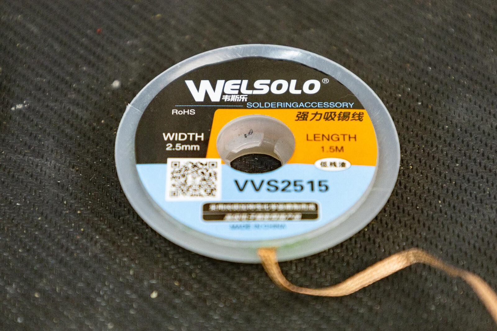
Place a section of solder wick over a pin. Press your iron onto the wick directly above the pin and hold for two to four seconds. You’ll see the solder wick up into the braid - it turns silver as it absorbs molten solder. Move to a fresh section of wick and repeat on the next pin.
Work methodically around all 14 pins. For ground pins you may need to hold the iron a little longer. If the wick isn’t absorbing, add more flux - that almost always means oxidation is blocking the flow. What it does not mean is that you should push harder.
As an alternative to wick, you can use a manual spring-loaded solder sucker. Heat each pin with the iron and quickly trigger the sucker to vacuum the molten solder. This takes dexterity - you need to pull the iron and land the sucker inside about a second, before the solder sets again.
Stage 5 - Free the Module
After wicking all pins, gently test whether the module is free. If it’s still held, re-flux the stubborn pins, add more leaded solder, and wick again. Repeat until every pin is clear.
Never lever it. If the module resists, a pin is still soldered, and prying is how the pad comes off.
Common Iron-Only Mistakes
Using a pointed or conical tip. These have poor heat transfer surface area. A chisel or screwdriver tip makes a massive difference when wicking solder.
Using an underpowered iron. If the tip temperature collapses the moment it touches the pad, you’re not going to win. See the section above on why a T12 is the floor and a C245 is better.
Using old, oxidised solder wick. If the wick has gone dull and dark, it won’t absorb effectively. Use fresh wick and store the roll in a sealed bag between sessions.
Not enough flux. Apply it generously and reapply every few pins. Flux is cheap. Boards are not.
Rushing. This method is slow by nature. Accept that and work methodically. Rushing leads to excessive heat application and board damage.
Method 3: Hot Air Reflow (Avoid This One)
A lot of guides put hot air at the top of the list for this repair. In theory it’s lovely: all the pins reflow at once, the module lifts off in one piece, done in two minutes.
In practice, here’s what happens. To get every pin on that footprint hot enough to release simultaneously, you have to soak the whole area, which means dumping heat into the entire board and its ground plane. And here’s the part that should give you pause. The module isn’t even in the airstream. You’re working the underside, the pin side, while the plastic module body sits against the opposite face of the PCB. It still melts. The ALPS body softens, slumps and deforms purely from heat conducted through the board, and instead of lifting a component off a PCB you’re now picking congealed plastic out of the pads and holes with tweezers.
Sit with that for a second, because it tells you exactly how much energy this method puts into the board. Enough to melt plastic you never pointed the gun at.
There is nothing hot air does on this particular job that a desoldering gun doesn’t do better, cleaner and with less heat in the board. Our advice is simple: don’t use it here.
If you are going to use it anyway - because it’s the only station you own, and sometimes that’s just the situation - then at least do these things.
Tape off everything you’re not trying to heat. This matters more than any temperature setting. Kapton tape over the surrounding board, the connectors, the ribbon sockets, any nearby plastic. Hot air does not go only where you point it, it spreads, and every square centimetre you cover is a square centimetre that isn’t being cooked. Be generous. Cover far more than feels necessary.
Take the nozzle off. This one is counterintuitive and most people get it backwards. A small nozzle feels like it should concentrate the heat, but what it actually does is choke the airflow. Less air volume means less heat delivered per second, which means you sit there holding the gun over the pin side for far longer, which means more total heat soaked into the board and more time for the plastic body on the far side to slump. Bare barrel, wide flow, get in and get out.
Use bismuth paste, generously. Cover all 14 pins and the grounding tabs. No flux on top of it, the paste is fluxed. The paste is what lets you work at 300-340°C instead of 380°C+, and on this method the difference between those two numbers is the difference between a module that comes off and a module that melts.
Preheat gently first. 200°C, low airflow, nozzle 4-5cm back, slow wide circles for 60-90 seconds. This brings the ground plane up to a baseline so you need less concentrated heat at the sharp end.
Then reflow. 300-340°C, keep moving in a tight slow circle 2-3cm above the pins, and start testing the module at around 20 seconds. Gentle pressure only, never lever it. If it hasn’t released inside 60 seconds, stop and let the board cool rather than pushing on - by that point you’re melting the module, not freeing it.
Never force it. If it resists, a pin hasn’t reflowed. Forcing it rips a pad or trace off the PCB, and that’s a far harder repair than the joystick swap itself.
Cleaning the Through-Holes
Whether you’ve got any work to do here depends entirely on which method you used.
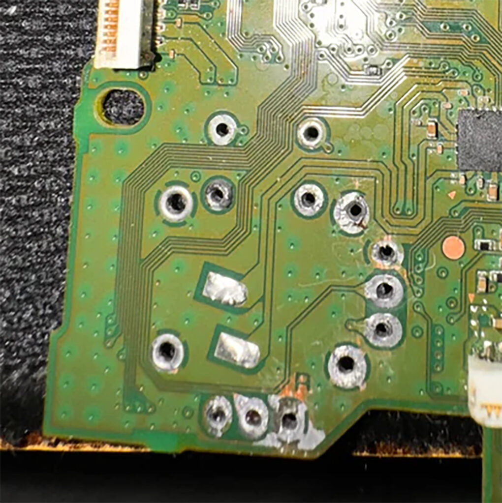
If you used the desoldering gun, you almost certainly don’t. The whole point of the vacuum is that the solder leaves the hole rather than being pushed around inside it, so what you’re looking at is 14 clean, open holes. Hold the board up to a light, confirm you can see through each one, and move on to the install.
If you used the iron and wick, or hot air, expect residue. Wick only takes what it can reach and hot air just melts solder in place, so there’s usually something left in the holes. The new module needs clean, open holes to drop into - if a pin won’t pass through, there’s still solder in the way.
Apply fresh flux to all through-holes. Use solder wick pressed onto each hole with your iron to draw out any remaining solder. Work from both sides of the board if needed.
If a hole is stubbornly blocked, add a tiny amount of fresh leaded solder to the hole, re-flux, and wick again. The fresh solder often mobilises whatever residue is stuck in the via.
Check that all 14 holes are clear by holding the board up to a light - you should be able to see light through each hole.
Installing the New Module
With the old module out and all through-holes clean, installation is straightforward - assuming you’ve got an iron that can do the job. This is the point where the T12 or C245 earns its money.
Apply a thin line of flux paste across the through-holes on the topside of the board. Flux genuinely matters on this side of the job.
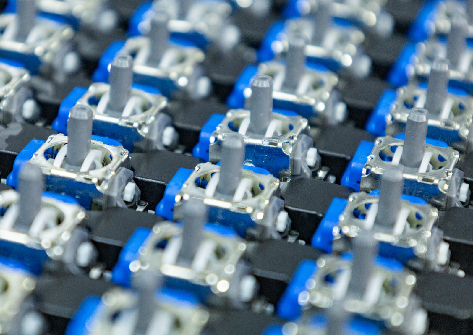
Drop the new module - whether it’s an OEM ALPS replacement or a TMR upgrade - into position from the topside. All 14 pins should pass through the holes cleanly and the module body should sit flush against the board with no gaps. If any pin doesn’t pass through, that hole still has solder in it. Go back and clean it.
Flip the board over or work from the underside if your PCB holder allows it.
Set your iron to 350°C with a chisel tip and use 63/37 leaded solder wire at 0.6mm. Touch the tip to the junction where the pin meets the pad, then feed a small amount of solder wire into the joint from the opposite side. The solder should flow around the pin and fill the pad. Hold for a second or two, then lift off.
If a joint refuses to flow and the solder just sits there in a ball, that is a heat delivery problem, not a technique problem. Check you’re on a chisel tip, check the tip is clean and tinned, and if the iron still can’t hold temperature against the ground pins, you’ve found the reason we bang on about cartridge irons.
A good joint looks shiny and slightly concave - a smooth volcano shape tapering from the pad up to the pin. A dull, blobby joint is a cold joint. Reheat it and add a touch of flux.
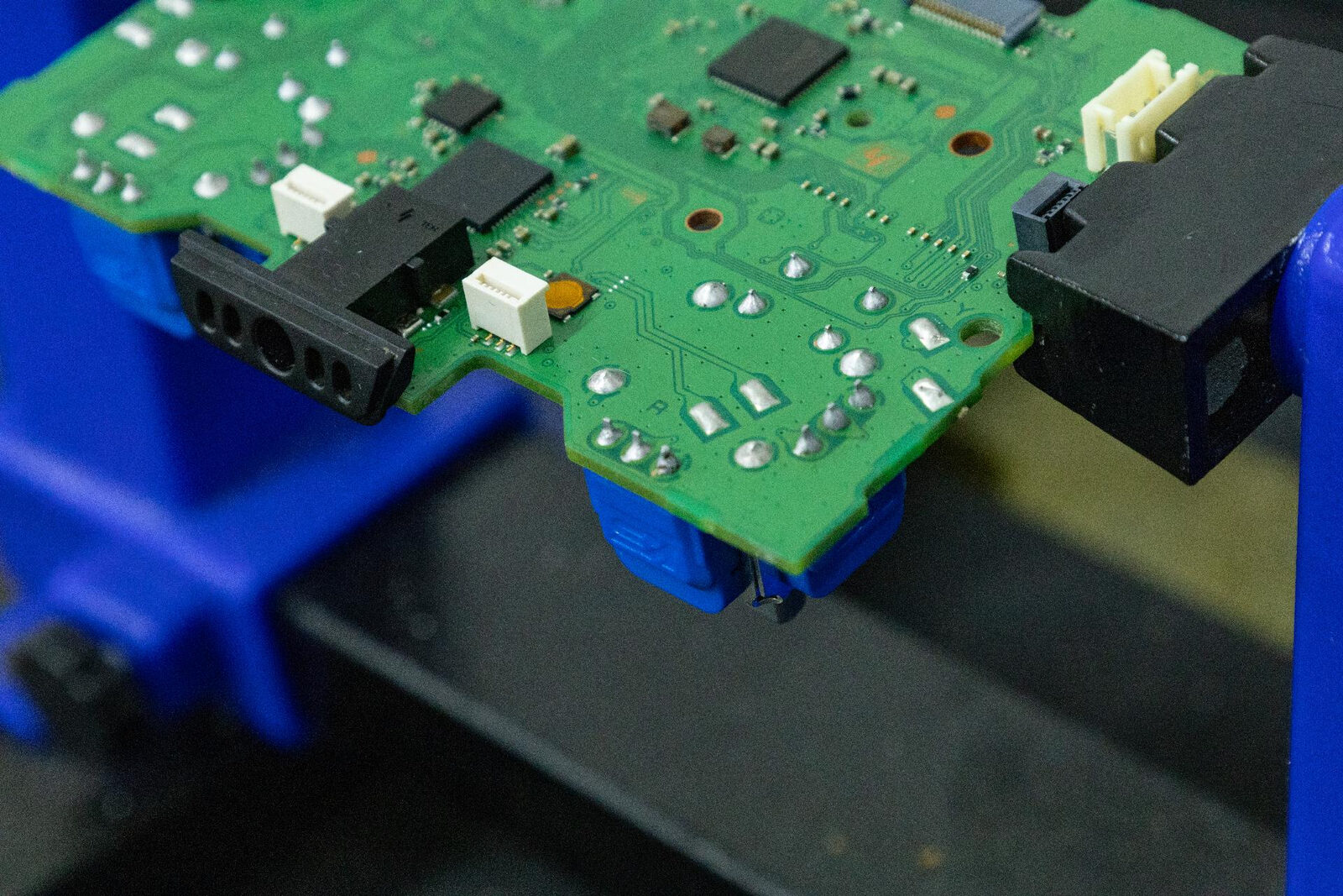
Solder all 14 pins one at a time. Inspect each joint visually as you go. Look for solder bridges - solder inadvertently connecting two adjacent pins. If you spot a bridge, add flux to the bridged area and run your iron between the pins to separate them, or use solder wick to remove the excess.
Clean flux residue with isopropyl alcohol and a small brush if desired. This isn’t strictly necessary with no-clean flux, but it makes visual inspection of the joints much easier and gives a more professional finish. An old toothbrush and 99%+ IPA is all it takes.
Method Comparison
| Factor | Desoldering Gun (Recommended) | Iron & Wick | Hot Air Reflow (Avoid) |
|---|---|---|---|
| Speed | Medium (5-8 min) | Slowest (10-15 min) | Fastest on paper (2-3 min) |
| Difficulty | Easy | Hard | Medium |
| Board damage risk | Lowest, heat only goes where you put it | Lifted pads if you press and linger | Highest, and it melts the module body |
| Bismuth paste | Strongly recommended | Essential | Essential |
| Flux on top of bismuth | Not needed | Needed once fresh solder goes on, for the wick | Not needed |
| Holes after removal | Clean and open, ready to fit | Residue, needs wicking | Residue, plus melted plastic to pick out |
| Best suited for | Everyone, beginners and pros alike | Experienced hands with a proper cartridge iron | Nothing on this repair |
| Key temperature | 280-320°C tip with paste | 320-350°C tip, chisel | 300-340°C air |
| Equipment cost | ~£50-80 (e.g. Yihua 948) | ~£40-80 (T12 station upwards) | ~£80-100 (2-in-1 station) |
Note that whichever removal method you pick, you still need the soldering iron to fit the new module. The iron is not one of three options, it’s the constant.
Tips for Your First Repair
If this is your first time desoldering a joystick module, start with a controller that’s already written off - a dead board, a parts unit, something you don’t mind destroying. Practice the full workflow on a board with no consequences before touching a controller you intend to keep or sell.
Use the desoldering gun method for your first successful repair, and probably every repair after that too. It’s the most forgiving approach, you can take your time on each pin without worrying about heat soaking the entire board, and it doubles as a tool for tidying up solder joints on the install side. A Yihua 948 or similar dedicated desoldering station is one of the best investments you can make for controller repair work.
Don’t skip the bismuth paste. It genuinely transforms the difficulty of this repair from “wrestling with stubborn lead-free solder through a ground plane” to “everything just flows.” A syringe costs a few pounds and lasts dozens of repairs. And don’t waste flux on top of it - the paste is already fluxed, and stacking flux over it does nothing but make a mess you’ll clean off later.
Spend the money on the iron before you spend it on anything else cosmetic. A T12 that holds 350°C under load is the entry point, a C245 is the tool you’ll be glad you bought. Removal is a solved problem once you own a desoldering gun. Installation is where a weak iron will quietly ruin the job.
If something isn’t flowing, the answer is almost never more temperature. It’s more paste, more flux, a better tip, or a bigger contact area. Heat is expensive - it costs you board health.
Finally, remember that the joystick module footprint is identical across every DualSense revision from BDM-010 through BDM-060. Unlike shells and triggers, you don’t need to worry about compatibility. One technique works on every controller Sony has shipped.
Related Guides
- PS5 DualSense Stick Drift: Causes, Fixes, and the TMR Upgrade - Why drift happens, ALPS vs TMR vs Hall Effect module comparison, supplier recommendations, and post-repair calibration
- PS5 DualSense Controller BDM Revisions: The Complete Guide - Identifying your controller version and understanding internal differences
- PS5 DualSense Mods and Upgrades - Custom shells, clicky buttons, LED kits, and performance modifications
This article may contain affiliate links to Amazon, eBay and other retailers. I may earn a small commission from qualifying purchases made through these links at no additional cost to you.